
شبیه سازی های درایو های الکتریکی
در این وبلاگ می توانید شبیه سازی درایو های الکتریکی را دریافت نمایید
شبیه سازی های درایو های الکتریکی
در این وبلاگ می توانید شبیه سازی درایو های الکتریکی را دریافت نمایید72 : آموزش اطلاعات مندرج در فیوز ها
Complete Guide to NH Fuses
What are NH Fuses?
NH fuses (also known as NH Knife Blade Fuses or DIN NH Blade Fuses) were defined in the German DIN standard 43620 around 1944. They were primarily designed as general purpose fuses for the protection of conductors. NH fuses are one-time fuses, meaning once they have blown, they must be replaced with a new fuse with the same characteristics.
NH Fuse Construction.
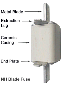
NH fuses are constructed from a rectangular ceramic casing enclosed by a cover plate that features a metal blade style terminal on each end. The fuse element inside the casing is connected to the cover plate / blade terminals. The majority of NH Fuses have a trip indicator to show if the fuse element has blown. Each cover plate includes a metal extraction lug that enables quick removal of the fuse from a holder when using the recomended NH fuse puller tool.
Where can I buy NH Fuses?
| Application | Type | NH Fuse Size | Voltage |
| General Purpose | gL / gG | 000 to 4a | 500VAC to 690VAC |
| Motor protection | aM | 000 to 4a | 500VAC to 690VAC |
| Semiconductor protection | aR / gR | 000 to 3 | 690VAC |
| Semiconductor protection | aR / gR | 00 to 0 | 1000VAC |
| Solar PV protection | gPV | 1 to 3 | 1000VDC |
| Battery protection | gS | 000 to 3 | 440VDC to 550VDC |
| Neutral Links | - | 00 to 4a | - |
NH Fuse Speeds.
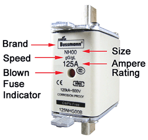
NH Fuses have evolved over the years to suit a wide range of applications. Currently NH fuses are available in a wide range of element speeds. The element speed is usually printed on the fuse casing as one of the following markings;
| aR, gR | Protection of semiconductor devices, Very Fast Acting fuse. |
| gL, gG | General Purpose, Fast Acting fuse. |
| aM | Motor Protection, Slow Acting fuse. |
| gPV | Protection of solar photovoltaic arrays. |
| gS | Protection of Batteries. |
| View all element speeds |
NH Fuse Sizes.
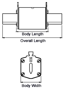
NH come in a variety of different sizes as you can see in the table below:
| Size | Body Type | Overall Length | Body Length | Body Width |
| NH 000 | Standard | 79 | 53 | 21 |
| NH 00C | Compact | 79 | 53 | 21 |
| NH 00 | Standard | 79 | 53 | 28 |
| NH 0 | Standard | 125 | 68 | 28 |
| NH 1C | Compact | 135 | 68 | 28 |
| NH 1 | Standard | 135 | 72 | 46 |
| NH 2C | Compact | 150 | 72 | 46 |
| NH 2 | Standard | 150 | 72 | 54 |
| NH 3C | Compact | 150 | 72 | 54 |
| NH 3 | Standard | 150 | 72 | 65 |
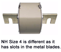
| NH 4 | Standard | 200 | 75 | 100 |
| NH 4a | Standard | 200 | 75 | 95 |
Dimensions (in mm) are based on ETI fuse range and may vary between brands.
NH Fuse Extraction.
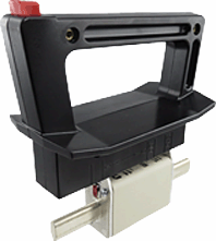
NH Fuse Holders.
UTILISATION CATEGORIES
If you've ever had to replace a fuse, you may have realised that there's a few different fuse speeds. In simple terms, 'fuse speed' tends to refer to the time between the moment that an overcurrent begins and the moment the fuse arcs and opens the circuits.
Most fuses can be considered to be fast acting, however there are also slow acting varieties, also known as 'motor fuses', 'time delay', 'slow blow', 'delayed action', etc and semiconductor protection versions, also known as 'ultra-rapid', 'solid state', 'rectifier', etc.
When it comes to official classifications though, you may be surprised to know that fuses are not classified in terms of 'speed' but more in terms of 'range' and 'application'. All fuses that are covered by the IEC standard have an utilisation category, and when selecting fuses, it's very important to get this right.
Fuses are marked with symbols denoting their particular application or characteristic.
First Letter (lower case)
The first, lower-case letter indicates the breaking range of the fuse.
"g" stands for full-range breaking capacity, meaning that the fuse is capable of breaking all overcurrents from its minimum melting current up to its breaking capacity. These fuses can protect from overloads and short circuits. Full-range breaking capacity fuses can be used as sole protective devices.
"a" stands for partial-range breaking capacity, meaning that the fuse is capable of only breaking high currents of a multiple of its rated current. Partial-range breaking capacity fuses are designed for short-circuit protection only, and are therefore used in combination with other devices providing protection against overcurrents. They are also frequently used for back-up protection of other switching devices having a lower breaking capacity (e.g. contactors or circuit breakers).
Second Letter (upper case)
The second, upper-case letter indicates the characteristic. Refer below.
Current Utilisation Categories
| Utilisation Category | Application (Characteristic) |
gG | Full range breaking capacity fuse for general application, mainly |
aM | Partial range breaking capacity fuse for the short circuit protection of motor circuits.
|
| gR | Full range breaking capacity fuse for the protection of |
| gS | Full range breaking capacity fuse for the protection of |
| aR | Partial range breaking capacity fuse for the short circuit |
| gB | Full range breaking capacity fuse for mining applications. |
| gTr | Full range breaking capacity fuse for transformer protection, |
| gM | Full range breaking capacity fuse for motor circuit |
| gN | North American general application fuse, mainly for cable |
| gD | North American general application time-delay fuse, mainly |
Former Utilisation Categories
| Utilisation Category | Application (Characteristic) |
| gl | Former IEC time-delay fuse, replaced by gG. |
| gll | Former IEC fast-acting fuse, replaced by gG. |
| gL | Former VDE fuse for conductor protectionm replaced by gG. |
| gRL | Manufacturer specific designation meanwhile standardised as gS. |
| gGR | Manufacturer specific designation meanwhile standardised as gS |
| gT | Former VDE time-delay fuse, replaced by gG |
| gF | Former VDE utilisation category, replaced by gG |
| gTF | Former VDE time-delay / fast-acting fuse, replaced by gB |
https://www.fuseco.com.au/fuses/resources/articles/utilisation-categories
What does I2t mean?
This is an extremely important figure in fuse specification. I2 is current squared whereas t is time. The figure shows how quickly the fuse reacts to different amounts of energy passing through it.
Or to put it another way, the I2t figure shows the amount of energy needed to operate the fuse. When you are specifying a fuse, you need to make sure that its I2t figure is smaller than the I2t of the equipment that it is protecting.

What are the differences between gFF, gG, gR, aM and aR fuses?
These letters all refer to the IEC international standard. They are all different types of fuses and relate to how they work.
gFF fuses have a thinner element so they are faster operating than gG fuses.gG is a general-purpose fuse that can cope with lower overload current faults but will clear high short circuit faults. They are not as fast operating as other fuses.
gR fuses have a thin copper link with M-Effect, so they provide some overload protection but are slower to operate for short circuits.
aM fuses are often used to protect electric motors. They have no M-Effect so are a lot more robust and can deal with the regular short overloads associated with something starting and stopping.
aR fuses have no M-Effect, but the element is so thin that the fuse will still blow quickly. This is a high-speed fuse that will clear a major fault in milliseconds. On the downside though, these fuses do tend to have a high watts loss during normal operation.
What is the difference between 415 V a.c. and 690 V a.c. fuses?
415V volts tends to be the industry standard voltage in the UK, but there are some bigger installations that need a higher voltage, for example if there are very long cable runs.
It’s important to know what the voltage rating is for an installation because you should never use a fuse beyond its stated rating. So, you can use a 690V fuse for lower voltage applications such as 415V, but you must not use a 415V fuse for higher voltages. 690V fuses tend to be larger and more expensive than the 415V options.
What is the difference between DC and AC?
This describes the type of voltage and current flow in a circuit. In DC, or Direct Current, the current only flows in one direction and is “always on”. For example a dc circuit at 50V will remain at 50V continuously until switched off. With AC, or Alternating Current, on the other hand it changes direction many times per second, typically 50 times a second. This means that for alternating currents the voltage also reverses when it changes direction.
This is important because alternating current will pass though zero volts at some point. Ac is used for most applications and fuses generally have an a.c voltage rating. As the voltage and current pass through ero (typically 50 times a second) it is slightly easier for a fuse to break this voltage and current in a faulted circuit. When you try break the circuit of a DC current it will carry on flowing in the same direction as there is no zero point. It will try to continue to flow and is very difficult to break. D.c rated fuses are generally longer as they are designed to handle difficult d.c voltages and currents.

What does a time current curve show you?
This is a graph that plots time on the y axis against current on the x axis. The graph shows you the operating characteristics of the fuse - or put another way how quickly the fuse will operate at a given fault current. So, higher overload currents will result in the fuse links element melting or vaporising more quickly.
If you look at the graph then any operating conditions to the left of the curve leaves the fuse intact, but anything to the right means the fuse has operated.


